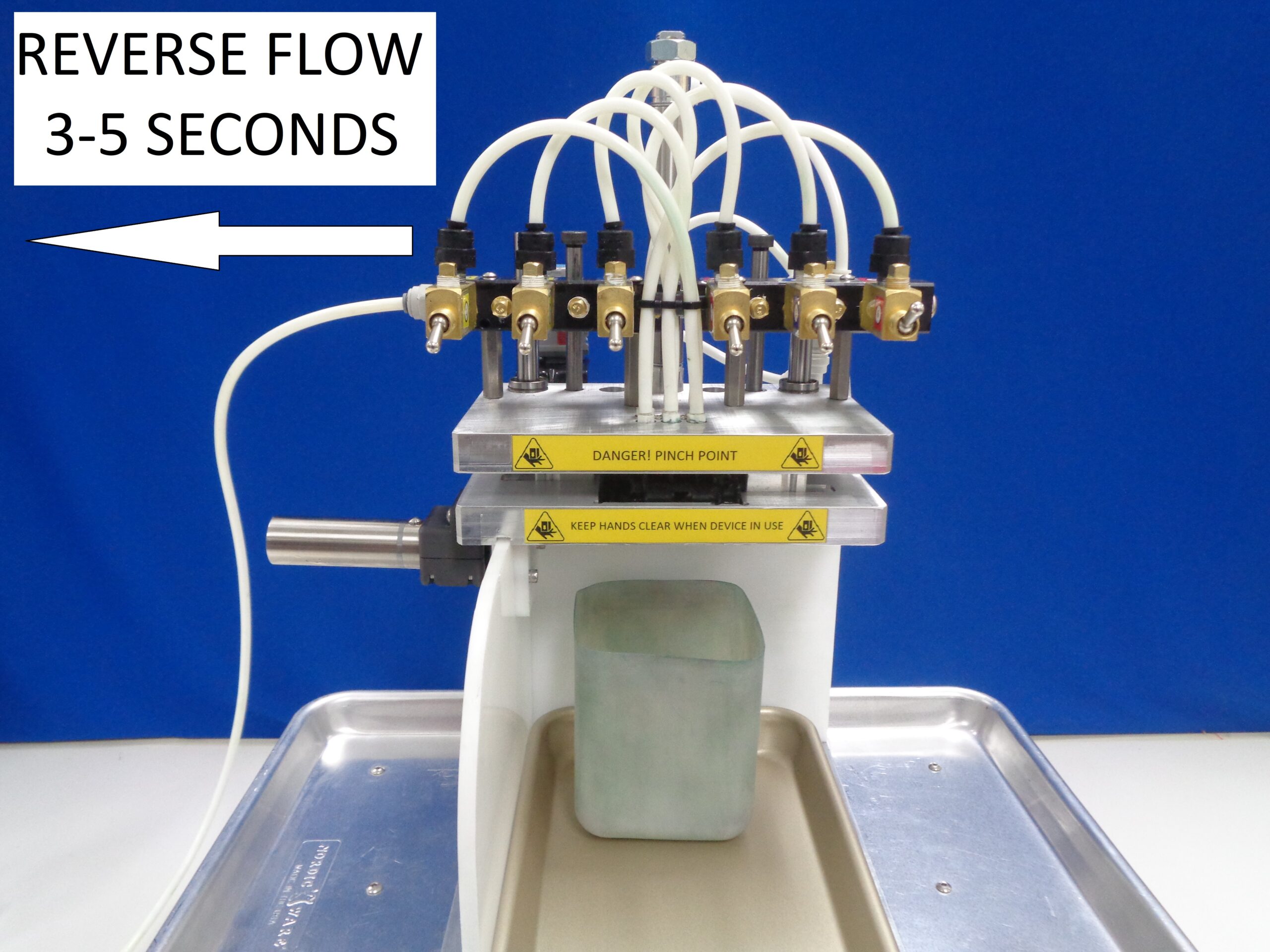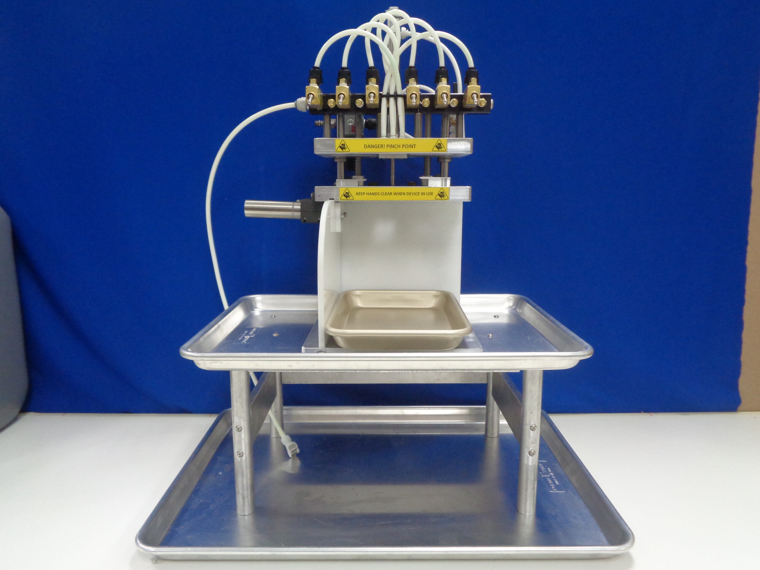
Flushing Rig with Stand
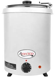
Soup Warmer
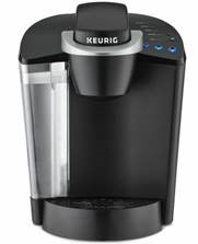
Coffee Maker (single cup)

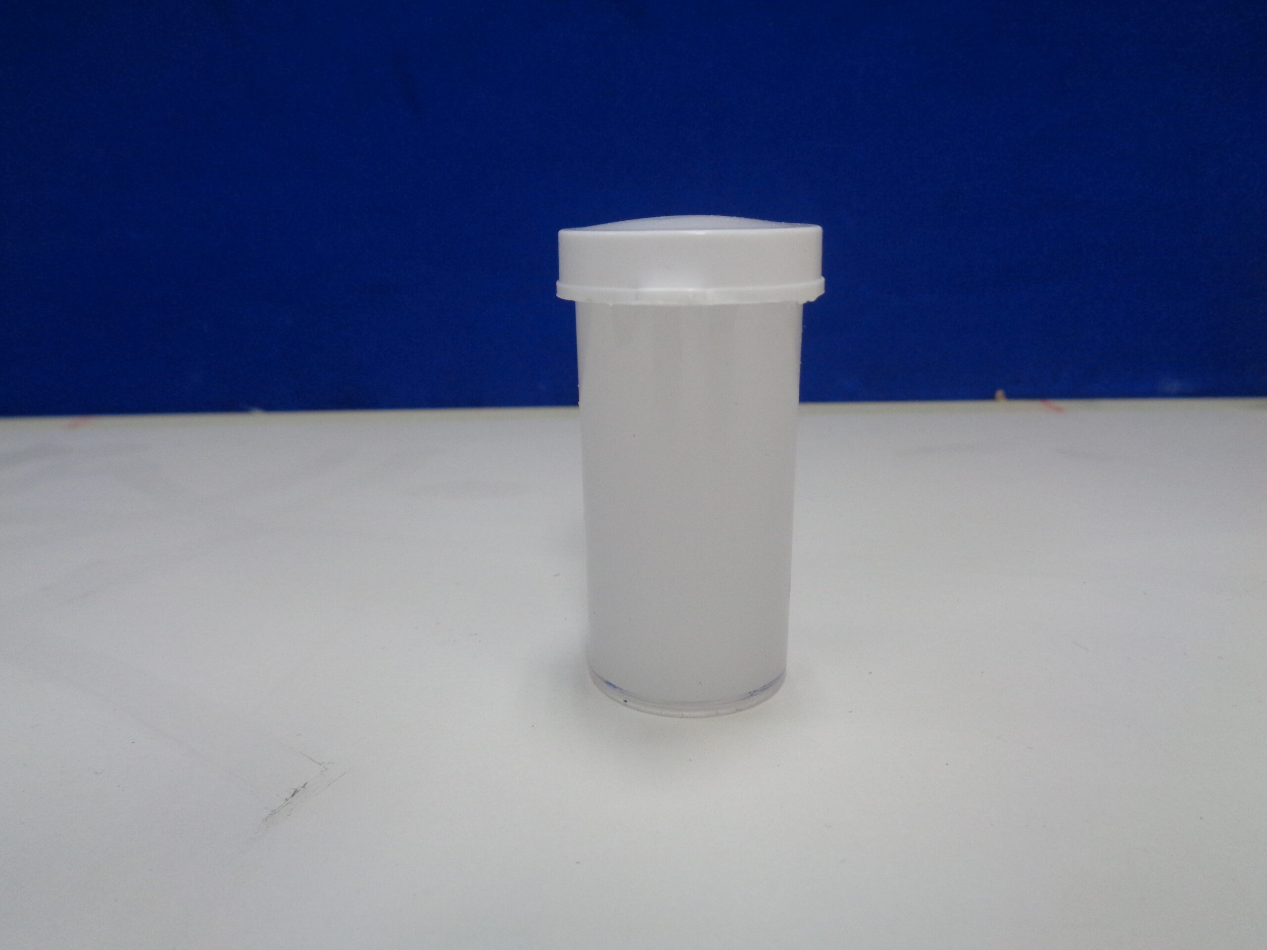
Wide Mouth Bottle

Glass bottles
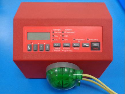
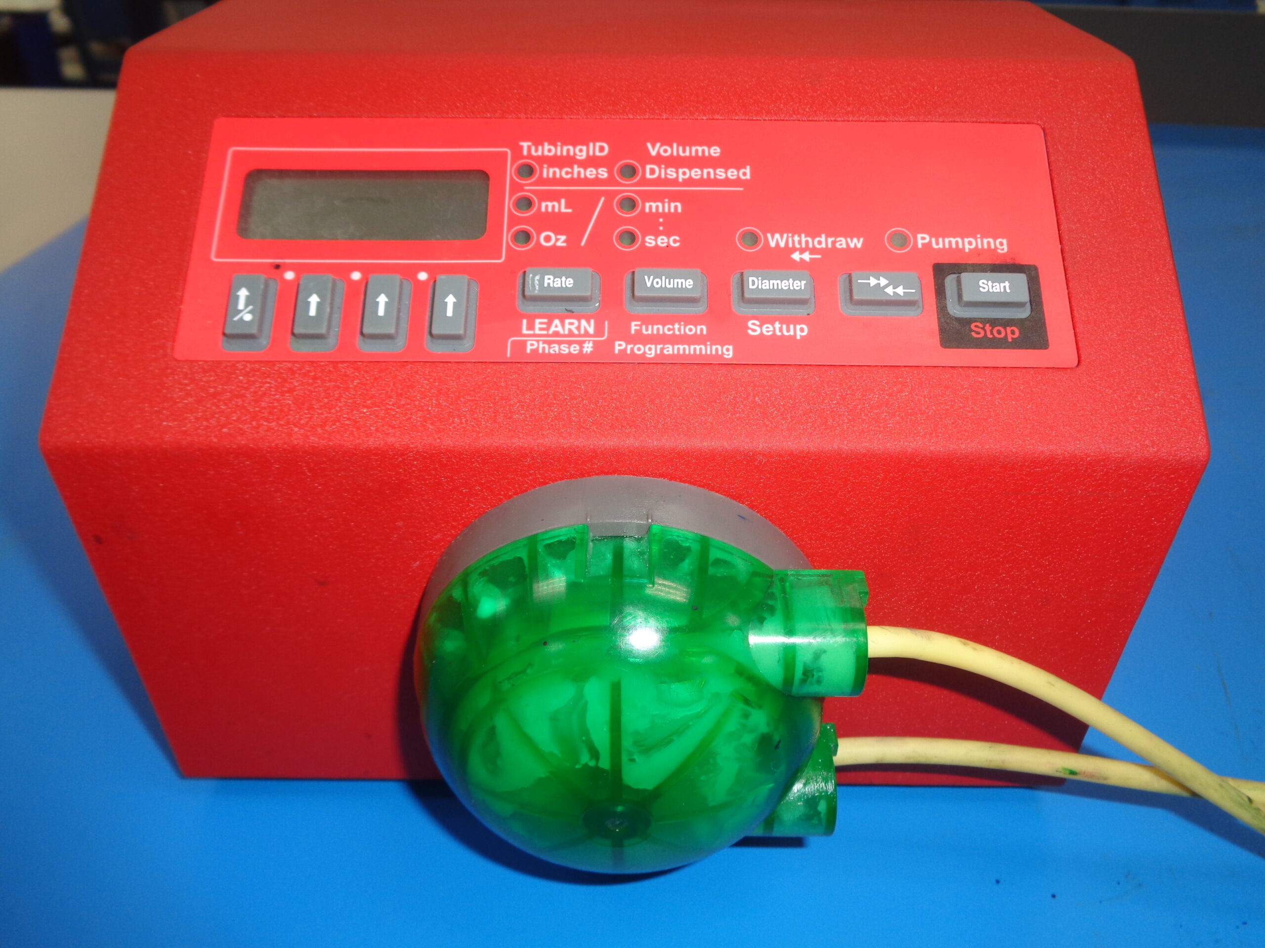
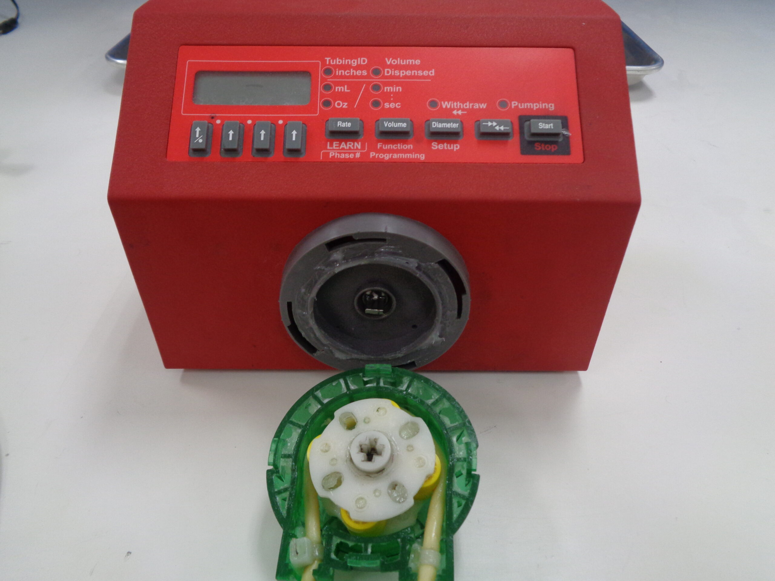
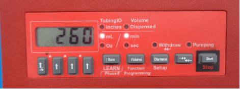
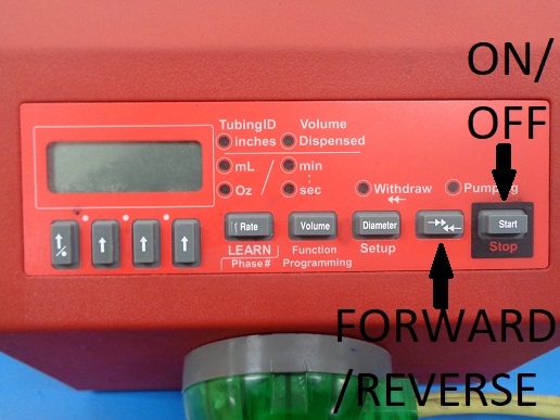
Peristaltic Pump
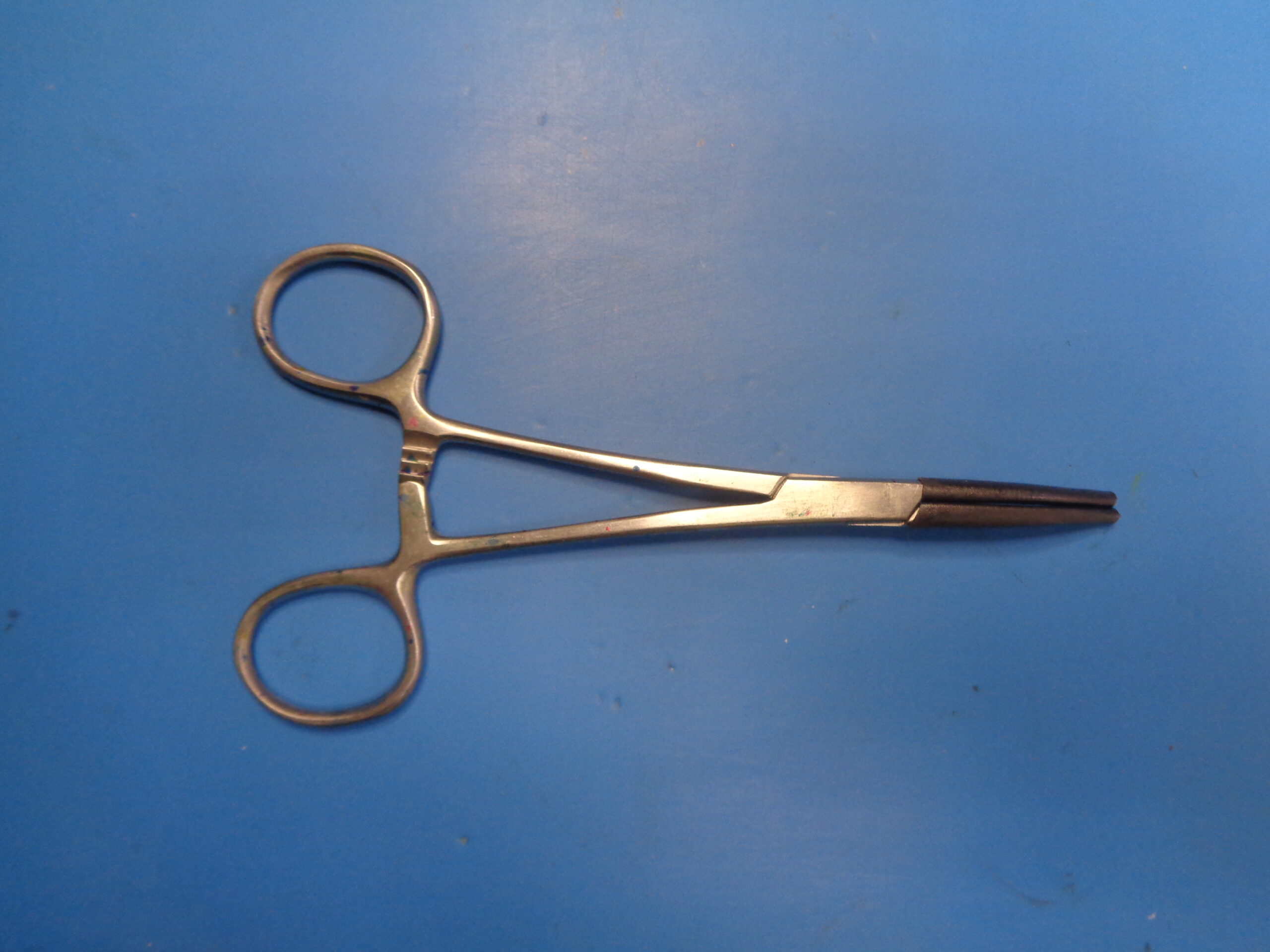
Padded Hemostats
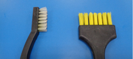
Soft Bristle Brush
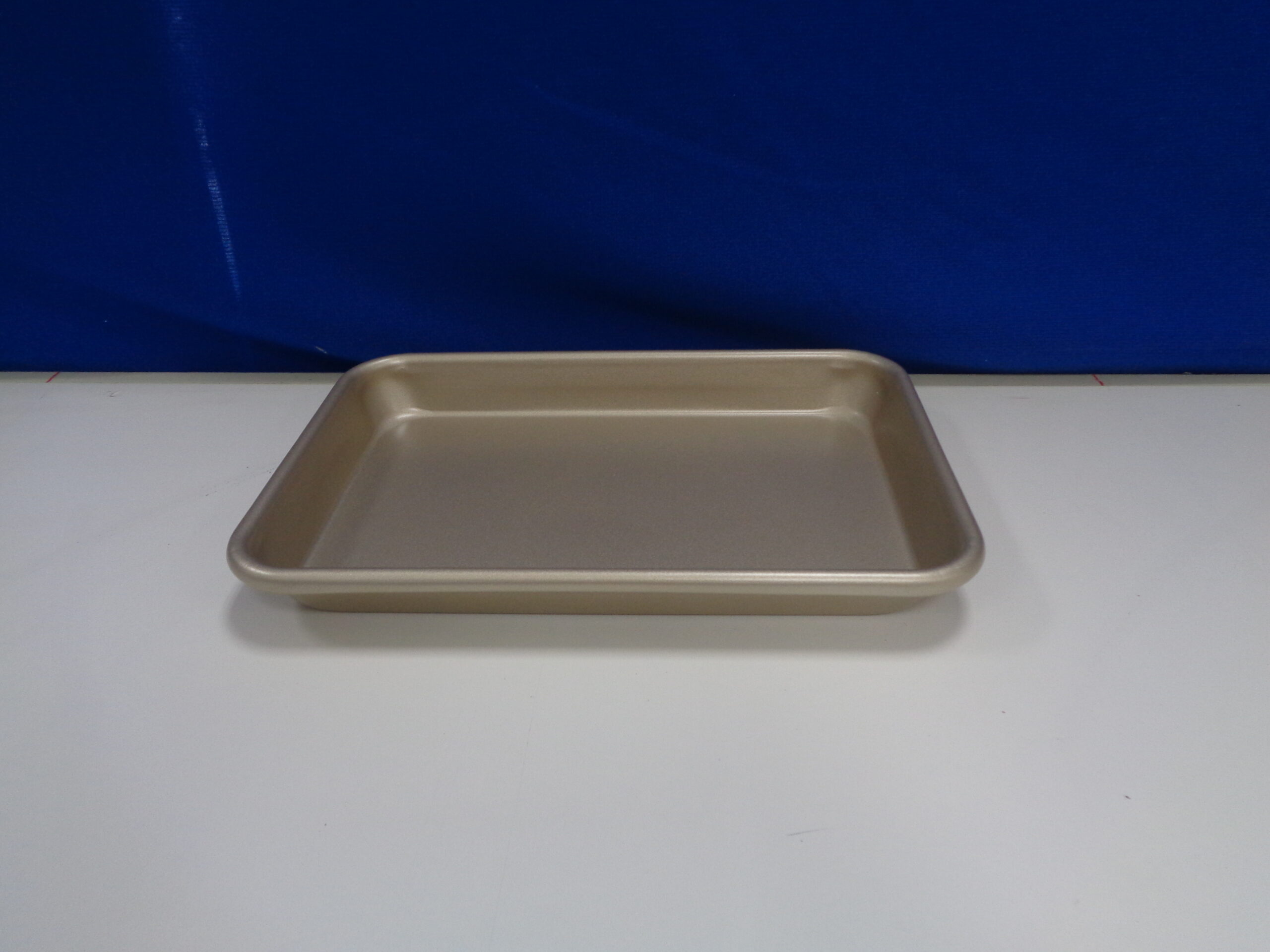
Small Tray
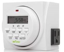
Programable Timer
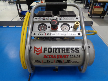
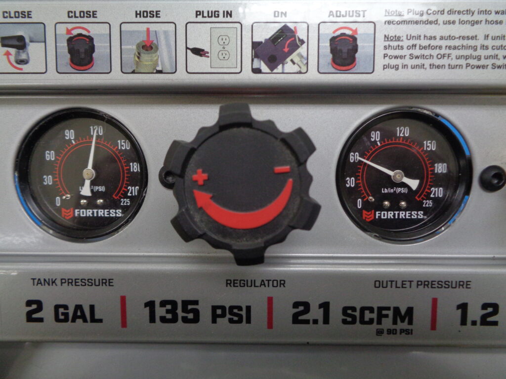
Air Compressor with hoses and regulator
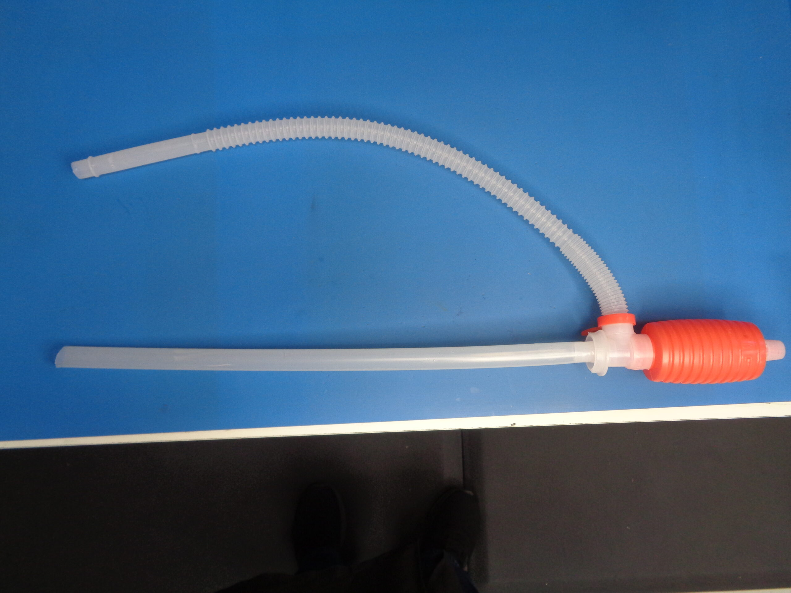
Hand Syphon Pump
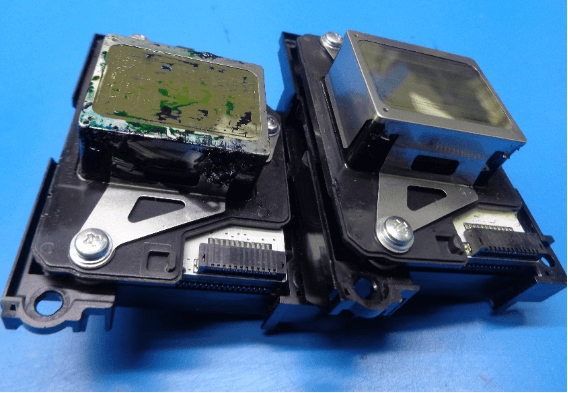
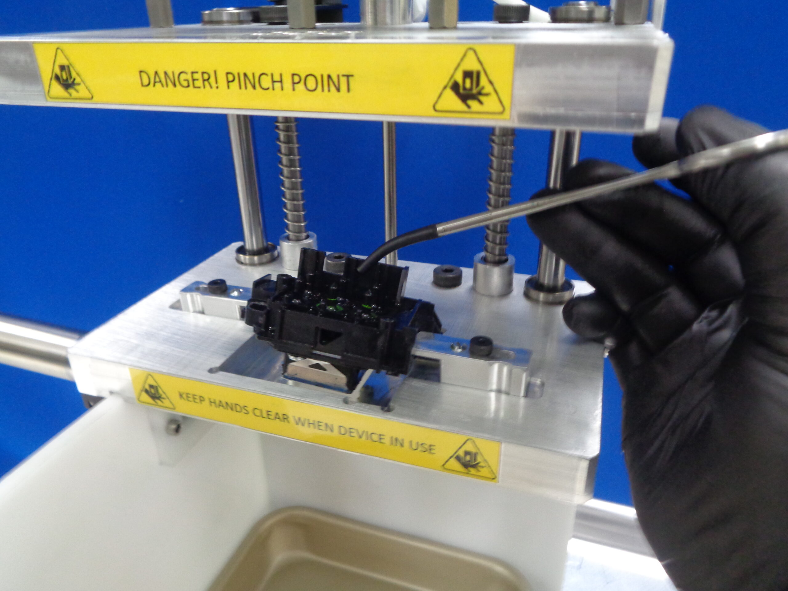
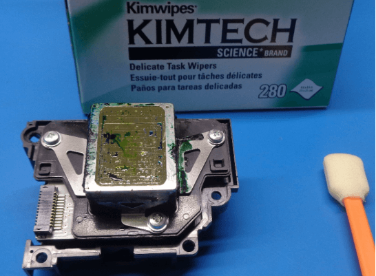
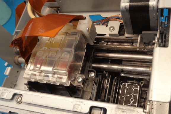
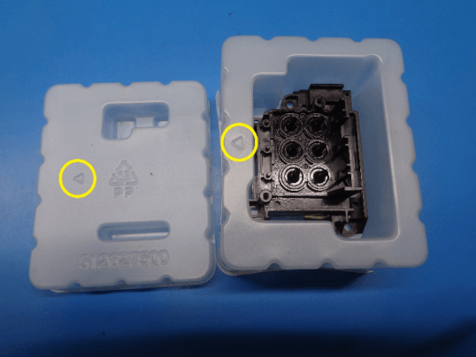
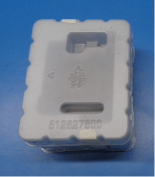
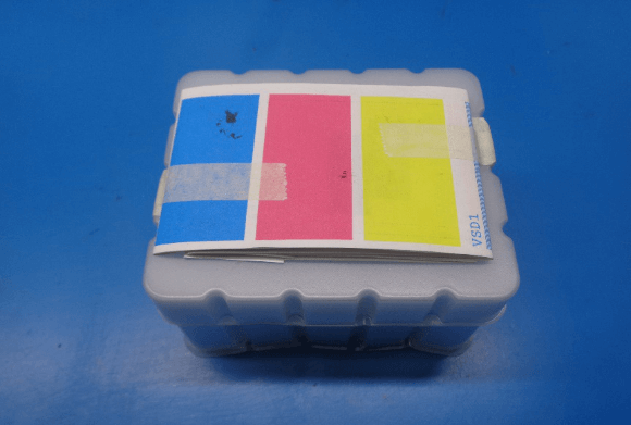
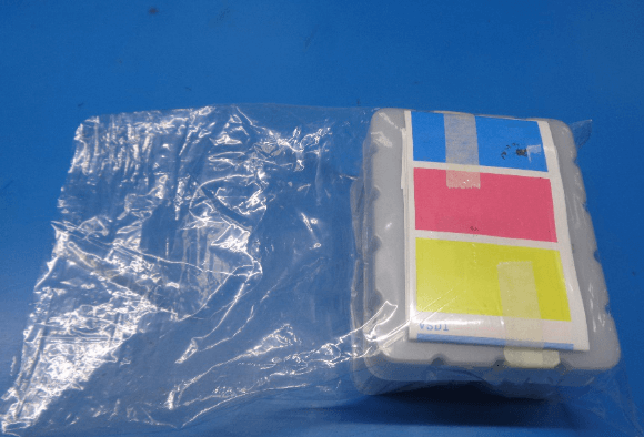
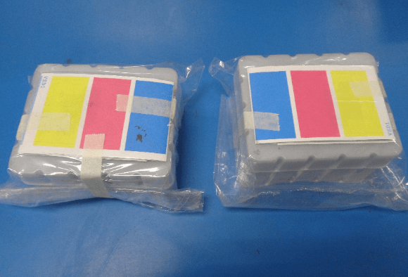
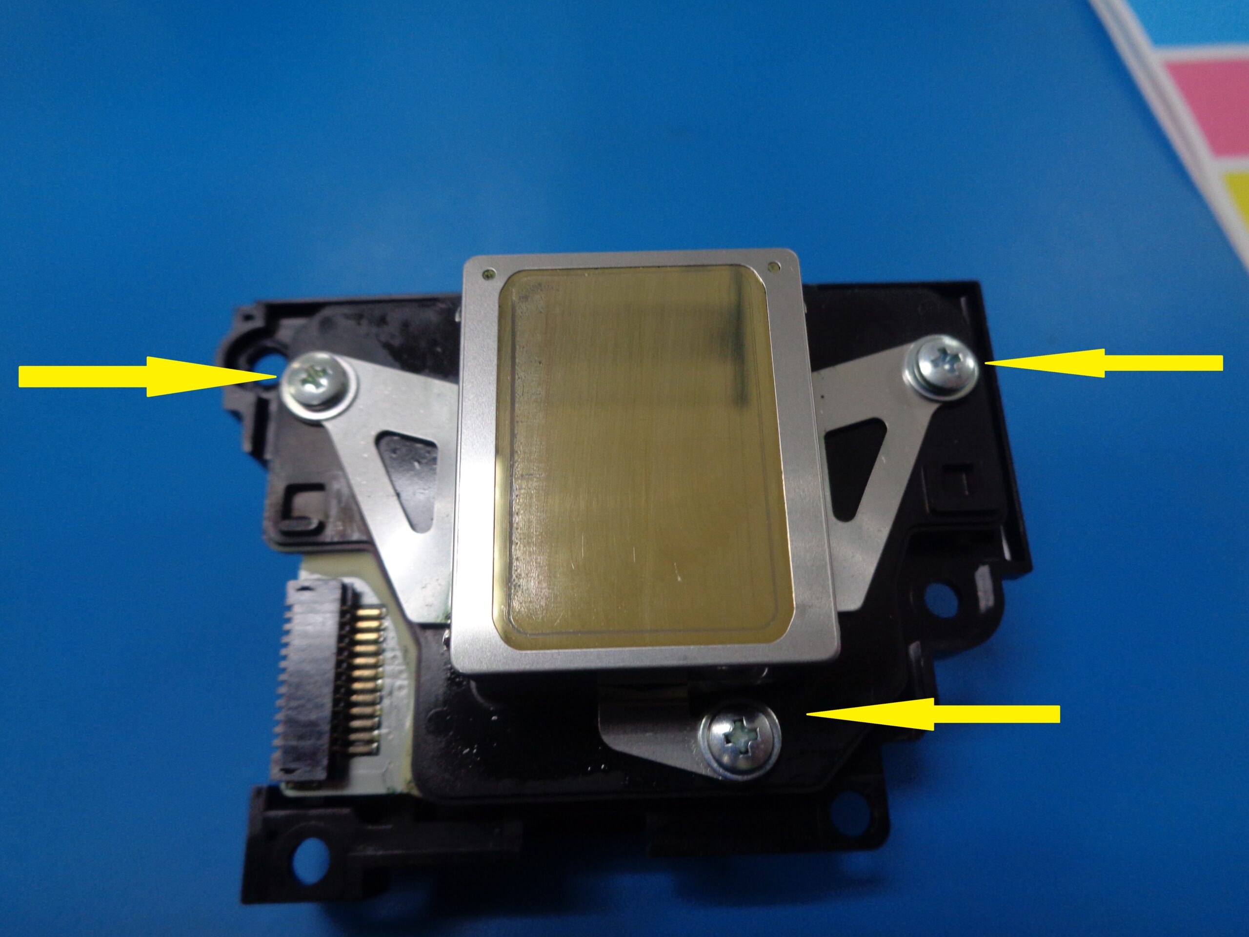
Print Heads
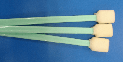
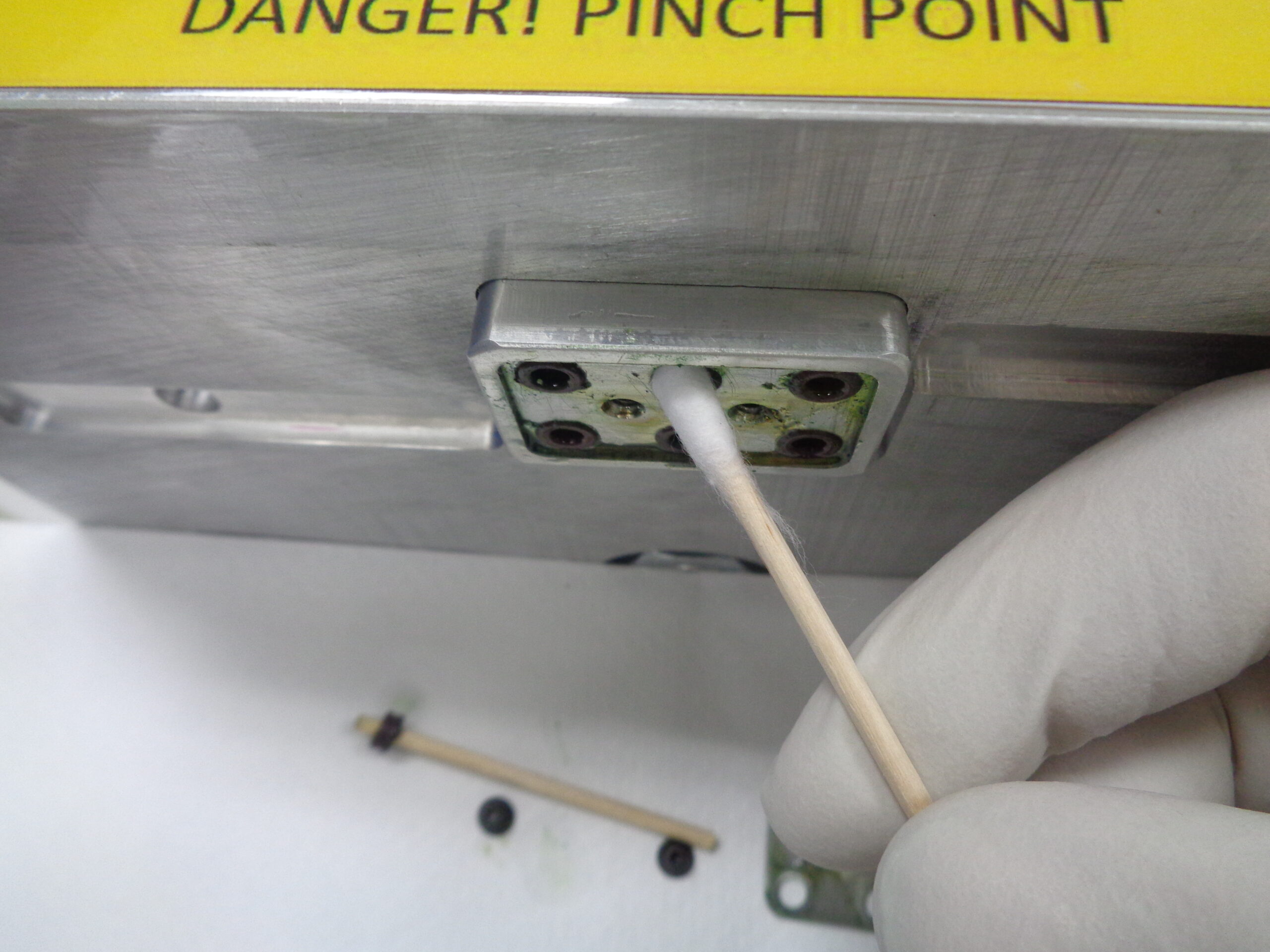
Foam Tipped Applicators

Plastic Scraper Blades
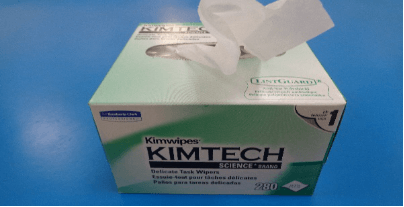
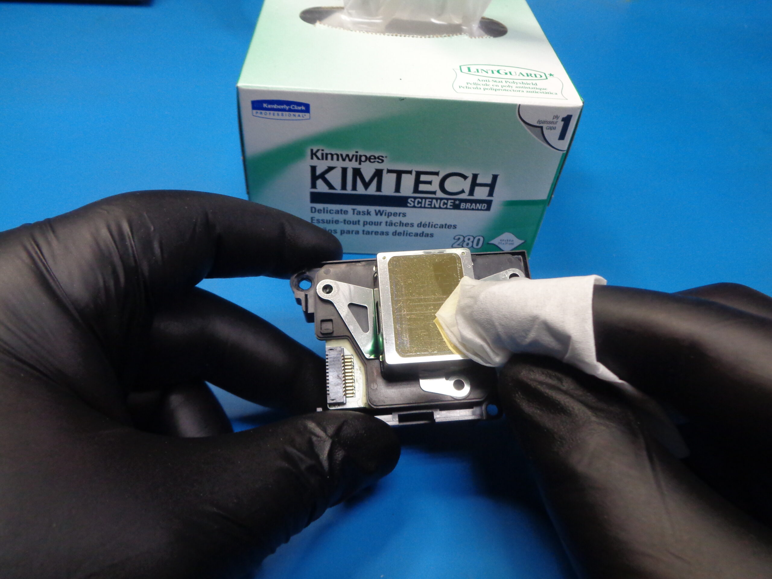
Lint-free Wipes
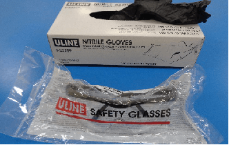
PPE (Gloves, Goggles, etc.…)
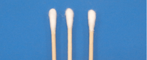
Cotton Tipped Applicators (shield only)
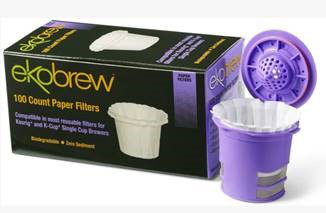
Coffee Filters (single cup)
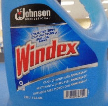
Windex (with ammonia)
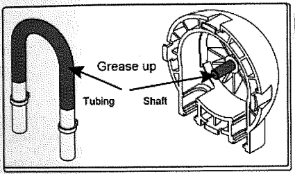
Peristaltic Grease
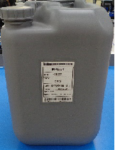
CR02
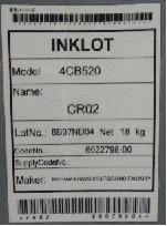
CR02 Label
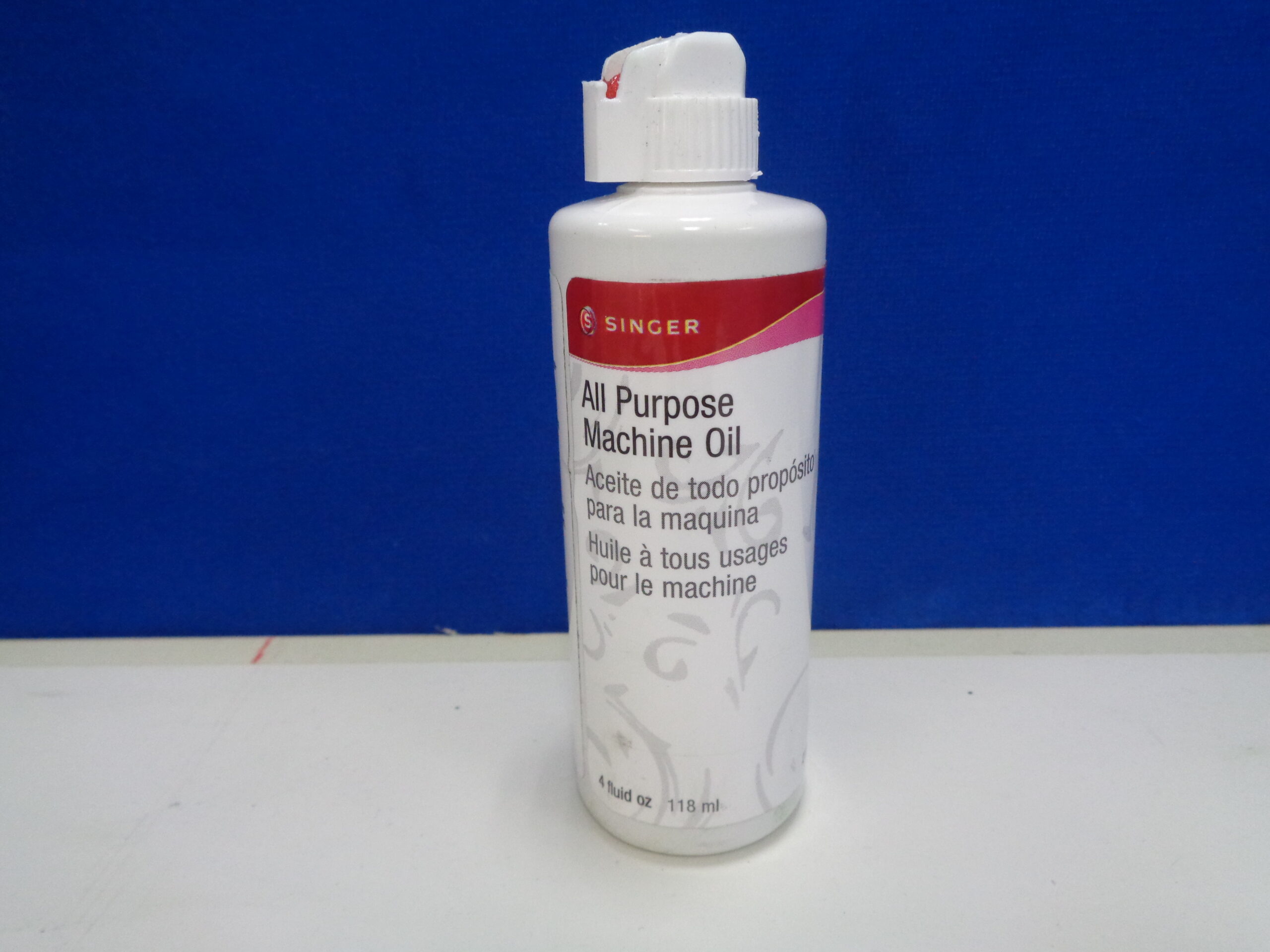
All Purpose Machine Oil


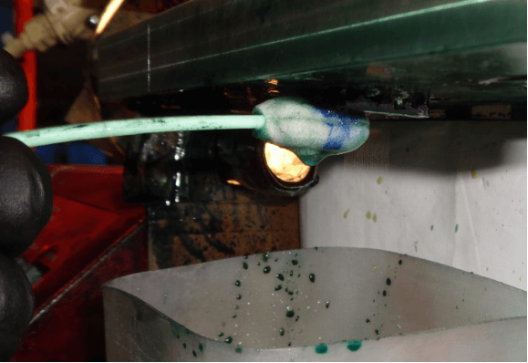


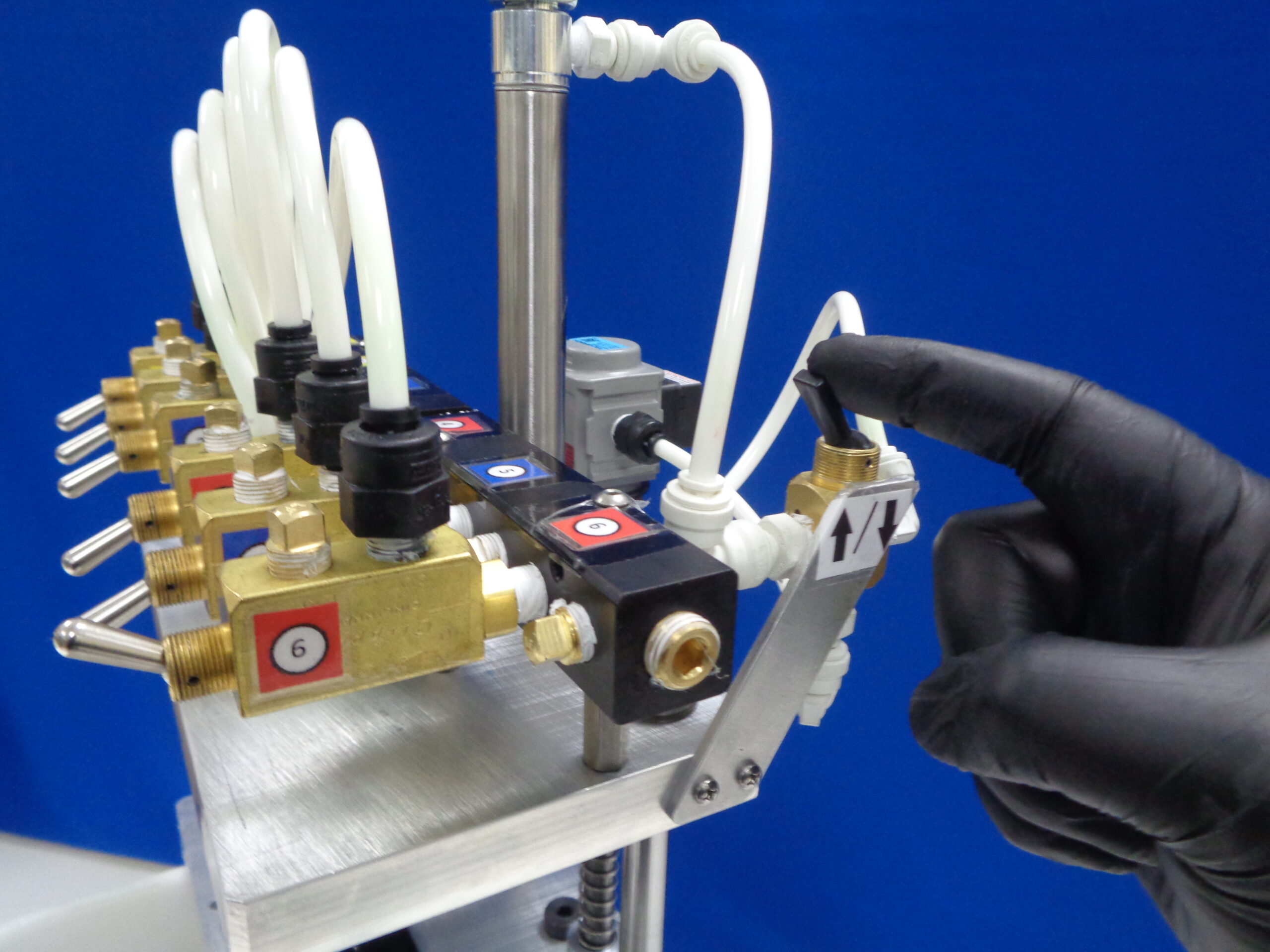
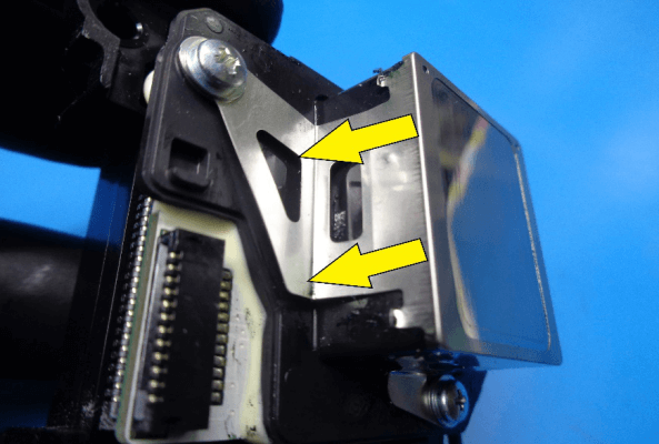
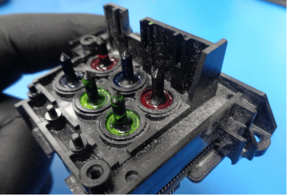
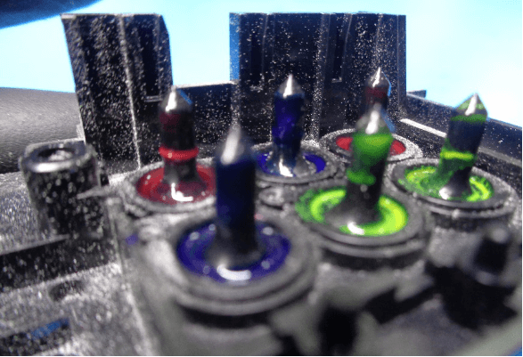
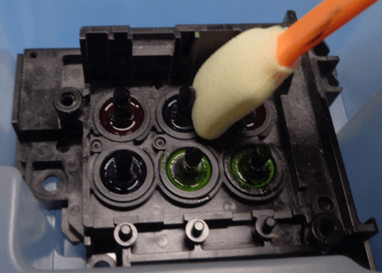
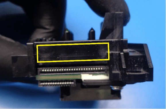
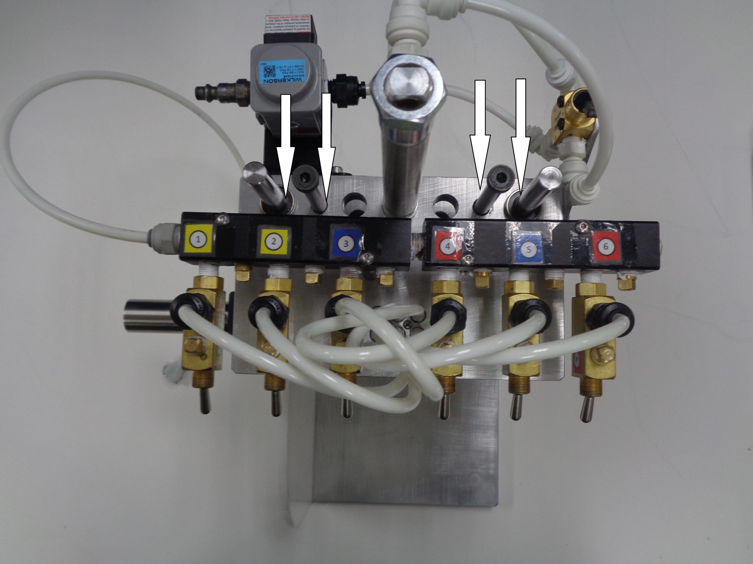
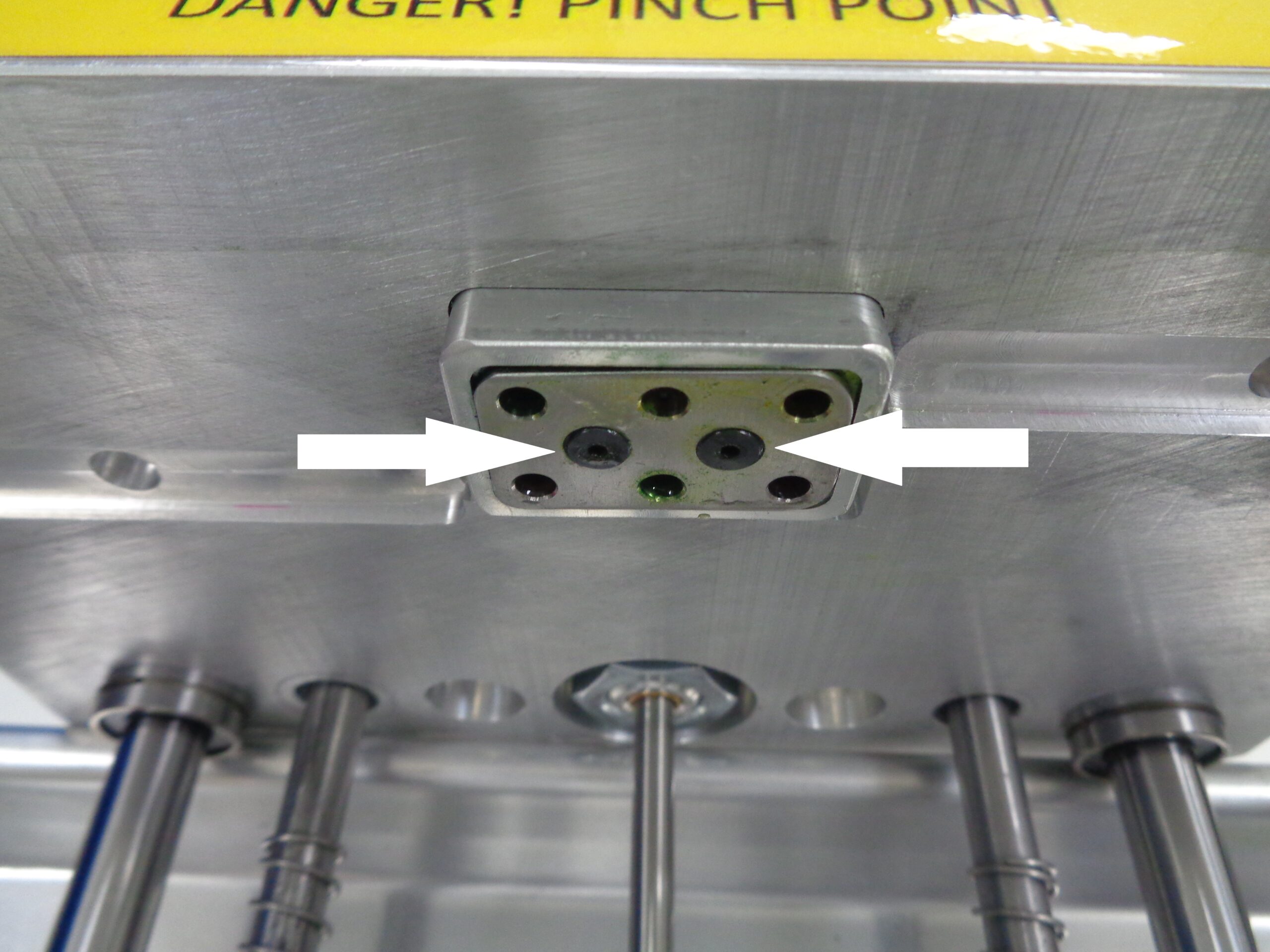
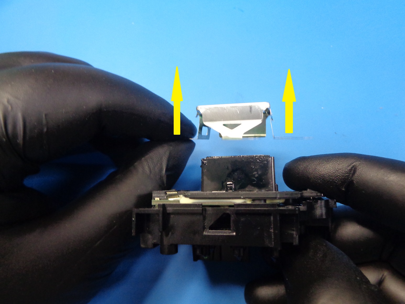
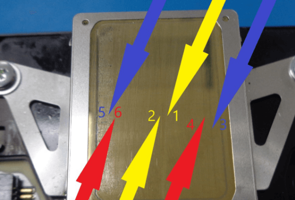
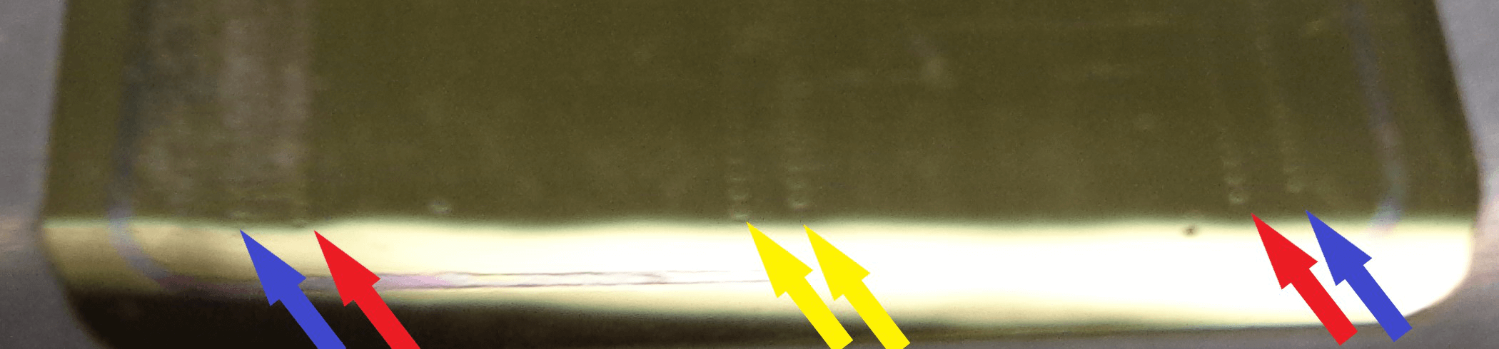
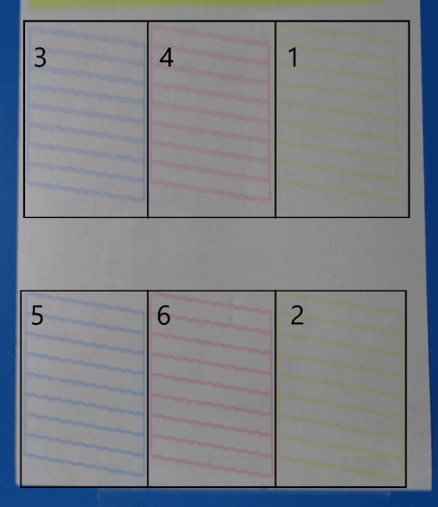
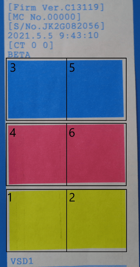
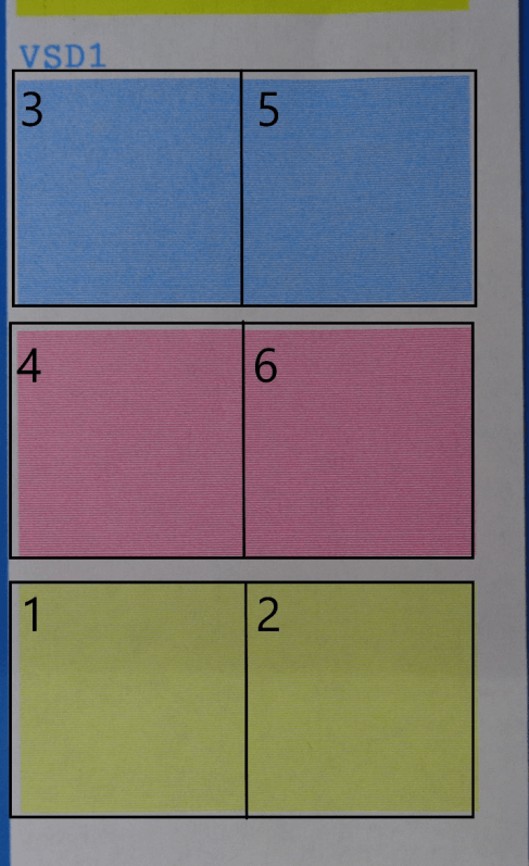
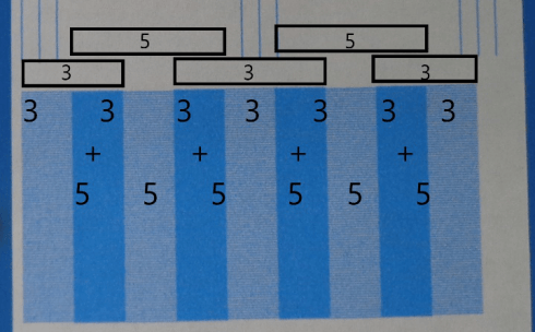
![]() Repeat process for nozzles 2-6
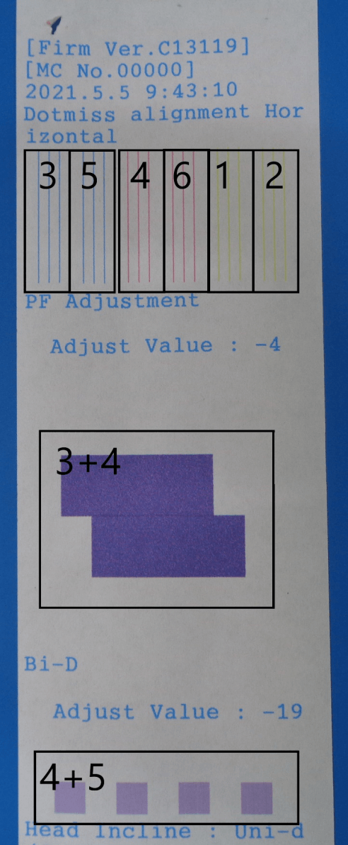
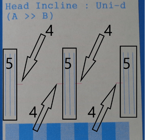
Repeat process for nozzles 2-6![]()